
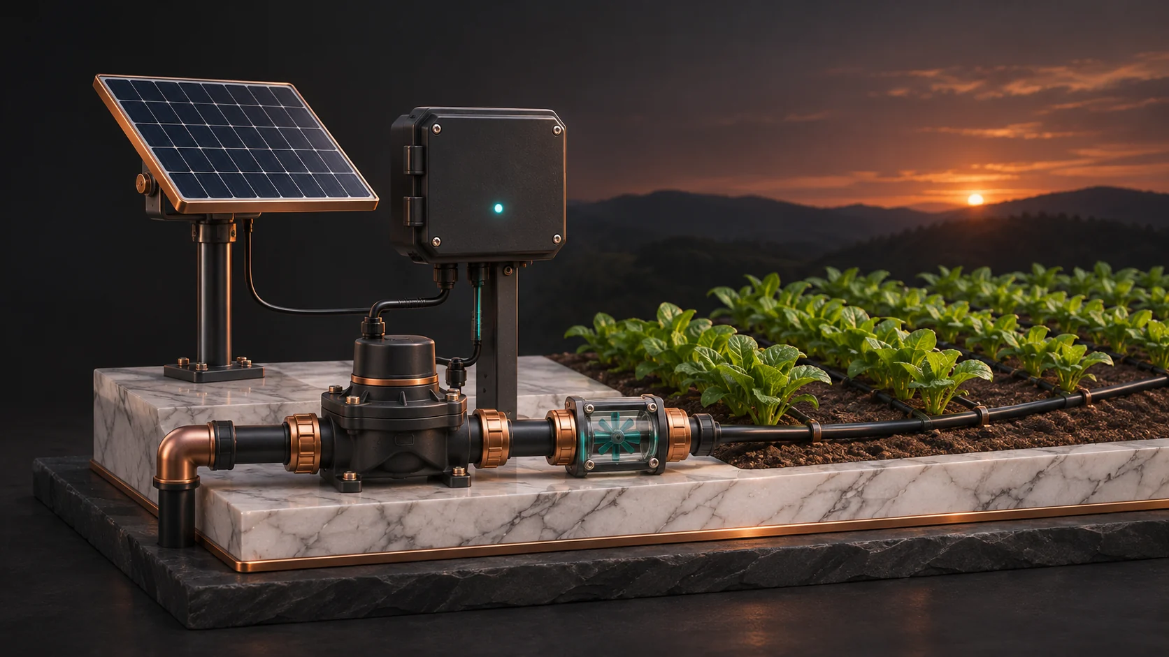
A remote irrigation station needs a way to verify flow and stop a failed run without waiting for a cloud reply. Use a locally enforced schedule with an expiry, maximum runtime and flow limits. Check the hydraulic response after opening and after closing. Where a stuck valve could cause significant damage, provide a separate approved way to isolate the water.
This guide is for irrigation managers, grounds teams, and integrators responsible for remote fields, parks, or golf course zones. Start by checking what the installed controller can already measure and stop. Run any new monitoring beside the existing system before giving it authority to request a change.
Choose where the valve and stop decisions belong
A supported wireless valve link or battery controller may fit where trenching is difficult. Confirm compatible valves, radio coverage, service modes, how a lost link is handled, and whether high- or low-flow protection is local to the appropriate controller. Hunter’s Wireless Valve Link specification is an example of a supported field-node system. Rain Bird documents station flow detection on a particular controller. Check the exact model’s offline behavior rather than assuming that all wireless systems supervise flow in the field.
An ESP32-WROOM-32UE is a candidate for local event logging, pulse counting and supervision over a documented controller interface. The Espressif module datasheet identifies the external antenna connection and its built-in 2.4 GHz radios. LoRa needs a separate compatible radio. Favor an existing controller with an approved local stop input when it can meet the requirement. A custom supervisor is justified when it adds a specific function you can verify and maintain. Keep pump protection, pressure relief and other existing protective functions independent.
Make the offline schedule valid only within agreed limits
Build the irrigation plan using crop and soil conditions, measured rainfall, delivered water, and an appropriate estimate of crop evapotranspiration. Reference ET multiplied by a crop coefficient can estimate crop water use. The coefficient, root-zone storage, runoff, recent rain and the delivery rate can all change the decision. University of Minnesota Extension explains the water-balance method. Use that information to propose a schedule. Local limits still determine whether the station can run.
- Scope each plan. Store the device and zone, approved start window, duration and volume limits, effective period, and a version. Authenticate incoming plans and keep the last accepted version and executed run IDs across resets. Reject mismatched, expired, older or repeated instructions. Use the same protections on MQTT or LoRaWAN so reconnecting does not start a previous run.
- Separate calendar time from run timing. Check that the local clock is valid before starting an offline schedule. Use an elapsed-time limit for an active run so a clock correction cannot extend it. A lost clock, stale plan or uncertain restart should block unattended new starts. An active run should reach the approved stop or safe state under local control without waiting for synchronization.
- Keep network and field authority separate. For a LoRaWAN Class A station, downlinks are available only in receive windows following an uplink. A network acknowledgment can confirm message delivery at its own layer. It cannot confirm water started or stopped. See the The Things Network explanation of device classes. Keep immediate hydraulic decisions local and queue timestamped status updates for later delivery.
Measure the hydraulic response before and after a command
Install an approved flow meter and, where useful, a pressure transducer in locations selected by the irrigation designer. Establish the normal startup and closing curves for each zone and the combinations of valves that can run together. Check supply pressure, filters, meter placement and the flow range the sensor can resolve. High flow with falling pressure may point to a broken line. Low flow can have several causes, including a closed valve, plugged filter or low supply. A shared mainline meter can report an abnormal system total without identifying which zone caused it.
Use the meter’s documented pulse scale and a suitable input interface. An ESP32 PCNT peripheral can count the approved pulse signal after conditioning. Test pulse widths, count retention, rollover, and electrical noise. Convert a count to volume and divide by elapsed time. For a meter that yields one pulse per gallon, a 20-second window changes by 3 gallons per minute for each extra pulse. If you need to distinguish closer rates, use a finer meter output or a longer observation window and account for the effect on detection time.
In this illustrative trial, a zone normally settles near 21–24 gallons per minute. The node sees seven to eight pulses per 20 seconds after startup. During a later run, two settled windows have ten pulses each, or 30 gallons per minute, and measured pressure falls outside the established range. The site’s approved test procedure requests a stop locally. The controller records both the stop request and the measured decline afterward. If flow persists beyond the validated settling period, the separate approved isolation path and operator escalation take over. The trial numbers illustrate a decision method. They are not settings for another installation.
Plan for a latching valve that can stay open
A DC latching solenoid uses short drive pulses to switch state. Removing power may leave it latched in its last state. A successful pulse or a recorded current transient is evidence about the electrical command. Use measured flow, pressure and any supported position or latch feedback to establish the hydraulic result. After a restart, keep the state unknown until the system has verified it.
Match the actual coil and actuator to manufacturer requirements and verify close capability at the worst supply voltage, wiring loss, temperature and hydraulic condition. A 4,700 µF capacitor at 24 V stores about 1.35 joules in an ideal calculation using one-half of capacitance times voltage squared. That is only the stored energy. Useful energy depends on the remaining voltage, coil and driver behavior, wiring and conversion losses. It cannot establish that a valve will close. A 24 V charging example does not mean a particular coil accepts 24 V. The Hunter catalog shows how DC-latching coil specifications differ from ordinary irrigation solenoids.
Do not start a run when the available reserve cannot support the approved stop sequence. Verify worst-season solar input, shading, battery aging, temperature, repeated operations and radio retries. Measure the energy needed to complete the run and verify closure under conditions the installation will actually see. Have the irrigation designer determine whether an independent master valve or other isolation is needed, including how it is powered, how operators can use it, and how the system limits harmful pressure transients. Test the independent path with the supervisory device unavailable. The cloud and the same battery cannot be assumed available during that test.
Commission one zone and record what actually stopped the water
- Establish a reference. Measure startup, steady and closing flow and pressure with the current system. Verify the meter against a reliable volume reference and include varying supply pressure and approved simultaneous operation.
- Test when the network is gone. Use an approved commissioning setup to exercise a lost radio link, stale or repeated schedule, invalid clock, reboot with the valve open, low battery, and a valve that does not confirm closure. Observe the physical water response. Keep the responsible operator able to isolate the zone independently throughout.
- Set the operating handoff. Define what allows a new run, which conditions hold it for inspection, who gets the alert, and who may restore operation. Provide one record of command time, measured flow, close confirmation, and action taken. Keep unknowns visible after an outage.
- Compare the supported choices. Measure validated run completion, false stops, time to detect and isolate a failed run, water delivery and battery reserve. Compare the commercial wireless system and custom supervisor against those same results, including spares and service access.
A useful pilot shows that the station can finish or stop an approved run locally, verify what happened to the water, and leave a clear record for the person responsible for the next decision.